Pressure Zones and the Hydraulic Grade Line: How Distribution Systems Stay in Spec
The single most-cited regulatory number in distribution operations is "20 psi." That's the minimum pressure the Safe Drinking Water Act requires at every customer's service connection. Drop below it during a main break, a hydrant flush, or a fire flow, and the system has to issue a precautionary boil-water notice. The upper end, typically 100 psi or whatever the local code allows before pressure-reducing valves are required at the meter: exists because high pressure cracks pipes, blows out water heaters, and shortens the life of every fixture downstream.
Keeping every customer in that 20-to-100-psi window across a system that may span 800 feet of elevation change is what pressure-zone design is for. This guide covers the hydraulic concepts every operator needs: pressure head, the hydraulic grade line, pressure zones, and the math that ties them together.
Key takeaways
- Pressure head converts feet of water elevation to psi: 1 foot of water column = 0.433 psi, or 1 psi = 2.31 feet of water.
- The hydraulic grade line (HGL) is the elevation above sea level that the water surface would reach at any point in the system if a vertical tube were opened. The HGL minus the ground elevation at a point gives the pressure head at that point.
- Static pressure is the pressure when no water is flowing. Dynamic pressure drops below static during flow because friction losses pull the HGL down.
- Distribution systems split into pressure zones when elevation changes would otherwise push some customers below 20 psi or above 100 psi.
- Each pressure zone has its own storage tank, pump station, or PRV (pressure-reducing valve) feeding it. The boundary between zones is closed valves or a PRV.
- Practice with the distribution operator tests and the math practice test; see related concepts in the storage tank operations guide.
The pressure-head conversion
Every distribution operator needs this conversion drilled in:
1 foot of water column  = 0.433 psi
1 psi                   = 2.31 feet of water
That conversion is the bridge between elevation maps and pressure gauges. A customer's house sits 100 feet below the local storage tank's water surface. Their static pressure is:
100 ft × 0.433 psi/ft = 43.3 psi
A customer 60 feet above the tank water surface has a static pressure of:
−60 ft × 0.433 psi/ft = −26 psi
A negative number is impossible, what it really means is that the tank water surface is below the customer's tap and there's no pressure at all without a pump. Customers above the local tank's water surface need to be pulled into a different (higher) pressure zone, or be served by a booster pump.
Exam questions test this constantly. A house 280 feet below the tank water surface has a static pressure of 280 × 0.433 = 121 psi, already at the upper limit, before adding any pump pressure. That customer almost certainly needs a PRV at the meter.
The hydraulic grade line
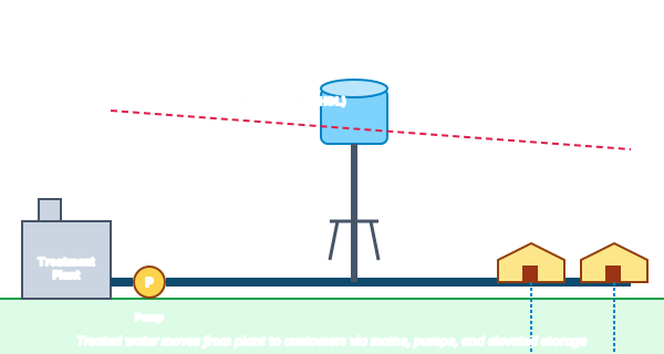
The HGL is the locus of water-surface elevations through the system. At a storage tank, the HGL is the tank's water-surface elevation. Downstream from a pump, the HGL is whatever elevation the pump's discharge pressure would push a vertical column of water to. As water flows through a pipe, friction drags energy out of it, and the HGL slopes downward in the direction of flow.
The pressure at any point in the system is:
Pressure (psi) = (HGL elevation − ground elevation at that point) × 0.433
Picture it as a virtual water surface floating above the pipe network. The HGL is what would happen if you opened a vertical tube at any point and watched where the water came to rest. Pressure at any customer's tap is the depth of that customer's tap below the HGL at that location.
This visualization is why distribution operators have so many topographic maps and HGL plots in their offices. To diagnose a low-pressure complaint, you don't reach for the customer's meter: you reach for the HGL plot and figure out whether the local HGL has dropped due to a friction loss, a closed valve, or a leak.
Static vs. dynamic pressure
When no water is flowing in a section of main, every point has its static pressure, set entirely by the elevation difference between the local tank water surface and the ground at that point. When water is flowing, a fire flow, a flushing operation, a peak-demand morning: friction in the pipes drags the HGL downward, and pressure at the far end drops.
The pressure customers actually see during peak demand is the dynamic pressure, which is always lower than the static. A well-designed system keeps even the worst-case dynamic pressure above 20 psi. A poorly-designed (or aging, undersized) system can drop below 20 psi during fire flows, triggering boil-water notices.
Operators measure dynamic pressure during flushing programs (see the distribution system flushing guide) and during scheduled fire-flow tests. The difference between static and dynamic pressure at a specific point tells you whether the local mains are sized adequately for demand.
Why systems split into pressure zones
A flat town with 20 feet of total elevation change can usually run as one pressure zone: one big tank up on the highest point, one set of mains, one HGL. But once elevation changes exceed about 130 feet, the math forces a split.
Consider a hilly town with 300 feet of elevation change. If you set the tank water surface 100 feet above the highest customer (to give them about 43 psi), the lowest customer 300 feet below the highest sees:
(300 + 100) × 0.433 = 173 psi
That's catastrophically high. Service lines would fail. Water heaters would leak. Fixtures would blow apart.
The solution is to split the system into multiple pressure zones, each with its own tank or feed source, sized so no customer in any zone sees more than ~100 psi or less than ~30 psi static. A typical large hilly system might have:
- Lower zone: served by the original treatment plant tank
- Middle zone: served by a booster pump that lifts water from the lower zone into a middle storage tank
- Upper zone: served by another booster pump that lifts water from the middle zone into a high-elevation tank
Zones are physically separated by closed valves, or connected only through PRVs that let the higher zone supply emergency water to the lower zone without backflow from low to high.
The three ways to feed a higher zone
-
Booster pump + dedicated storage tank. Most common for substantial elevation jumps. A pump station pulls water from the lower zone, lifts it to a tank at the higher elevation, and the higher zone is then gravity-fed from its own tank. Reliable but requires capital: pump station, tank, transmission main, telemetry.
-
Booster pump on demand (no dedicated tank). A pump runs whenever the higher zone's pressure drops below a setpoint. Cheaper but less reliable, if power fails, the higher zone loses water immediately. Used for small upper zones (a single neighborhood) where building a tank isn't justified.
-
Pressure-reducing valve (PRV) from a higher to a lower zone. Works in reverse, water flows from high to low across the PRV, which throttles to maintain a downstream pressure setpoint. Useful when a high-elevation source (mountain reservoir, for instance) needs to feed a lower-elevation distribution area. The PRV keeps low-zone pressures from spiking.
Pressure-reducing valves and pressure-sustaining valves
A PRV is a self-actuated valve that throttles to maintain a target downstream pressure. Set the PRV to 60 psi and it'll close as needed to keep its downstream side at 60 psi no matter how high the upstream pressure climbs. Common applications:
- Reducing pressure between zones, so the lower zone doesn't see the higher zone's HGL.
- Reducing pressure at individual service connections in valleys where static pressure exceeds plumbing code.
- Splitting a wide-pressure-range zone into a more controlled zone for sensitive equipment.
A pressure-sustaining valve (PSV) does the opposite. It throttles to maintain a target upstream pressure. Used to keep transmission mains from being drained by aggressive downstream demand: for example, a PSV at the outlet of a small storage tank can prevent the tank from being completely emptied during a fire flow, sustaining a minimum upstream pressure for other customers.
The exam doesn't always distinguish PRVs from PSVs sharply, but Class B and A questions will. Memorize: PRV protects what's downstream (limits high pressure); PSV protects what's upstream (maintains minimum supply).
Worked example: an operator pressure problem
Customer calls in: low pressure at their tap at 7:30 AM. Their house is at elevation 850 feet. The local pressure zone's tank water surface elevation is 950 feet. Static pressure should be:
(950 − 850) × 0.433 = 43.3 psi
The customer reports 18 psi. That's not just below the 20-psi minimum, it's a regulatory issue.
You drive out, attach a calibrated pressure gauge to a hose bib at the house. With no flow, the gauge reads 41 psi. With the kitchen sink running, it drops to 24 psi. With a garden hose at full flow, it drops to 16 psi.
Diagnosis: static pressure is normal (41 vs. theoretical 43, within gauge tolerance). Dynamic pressure drops sharply with flow. That means friction losses between the tank and this customer are too high. Causes to investigate:
- Partially closed valve somewhere upstream on the service main
- Aging galvanized service line with internal scale narrowing the bore
- A leak between the meter and the tap, drawing flow somewhere you can't see
- An undersized service line for the customer's current usage
This kind of diagnostic walk, start from the elevation map, compute the expected HGL, measure both static and dynamic at the complaint location, and reason about the difference, is the daily work of a distribution operator. It's also the framework the exam tests.
Pressure-related regulations
The federal floor is 20 psi minimum at every service connection at all times, including during fire flows and normal demand events (40 CFR 141.71 indirectly, and primacy-state rules). Many states have stricter rules, California's Title 22 sets a higher functional minimum, and most state primacy agencies treat 20 psi as the regulatory floor below which a boil-water notice is required.
There is no federal upper pressure limit. The upper limit comes from plumbing codes (typically 80 psi at the customer's connection, above which a PRV is required at the meter under the IPC) and from the utility's own desire to keep service-line failures down.
Most utilities target a working pressure range of 40–80 psi at the customer connection, with operating margins above 20 psi for fire flow and below 100 psi for plumbing code.
Common exam pitfalls
Mixing up feet of head and psi. The conversion is 0.433 psi per foot. Drop the decimal and you'll get wrong answers by a factor of more than 2. Memorize it.
Confusing static and dynamic pressure. Static is what the gauge reads with no flow. Dynamic is what it reads during flow. They are not the same number, and the difference tells you about friction.
Forgetting that the HGL slopes downward in the direction of flow. If the HGL didn't slope, water wouldn't flow. The slope is what overcomes friction.
Assuming pressure follows pipe elevation. Pressure follows the HGL minus ground elevation. The pipe could be running uphill while the HGL is running steeper downhill, flow direction is set by HGL slope, not pipe slope.
Treating PRVs and PSVs as the same valve. They throttle for different purposes. PRV protects downstream; PSV protects upstream.
Quick reference
- 1 ft of head = 0.433 psi
- 1 psi = 2.31 ft of head
- Minimum SDWA service pressure: 20 psi
- Plumbing code typical maximum: 80 psi (PRV required at meter above this)
- Target operating range: 40–80 psi at the connection
- HGL: water-surface elevation if a vertical tube were opened at any point
Practice and next steps
- Distribution operator practice tests: Grade 1–4, covering pressure, zones, and flow.
- Free water operator math practice test: pressure-head conversions and pump calculations.
- Storage tank operations and water age: companion guide on tank cycling and stratification.
- Distribution system flushing: what happens when dynamic pressure gets pushed by flushing programs.
- Free cross-connection practice test: backflow and pressure-related risks.
- Chemical dosage calculator: for chlorine residual math in distribution-system samples.
Pressure-zone design is the bones of every well-run distribution system. Once you can read an HGL and predict what every customer sees from the tank elevation alone, the rest of distribution operation falls into place.